Sensor Calibration
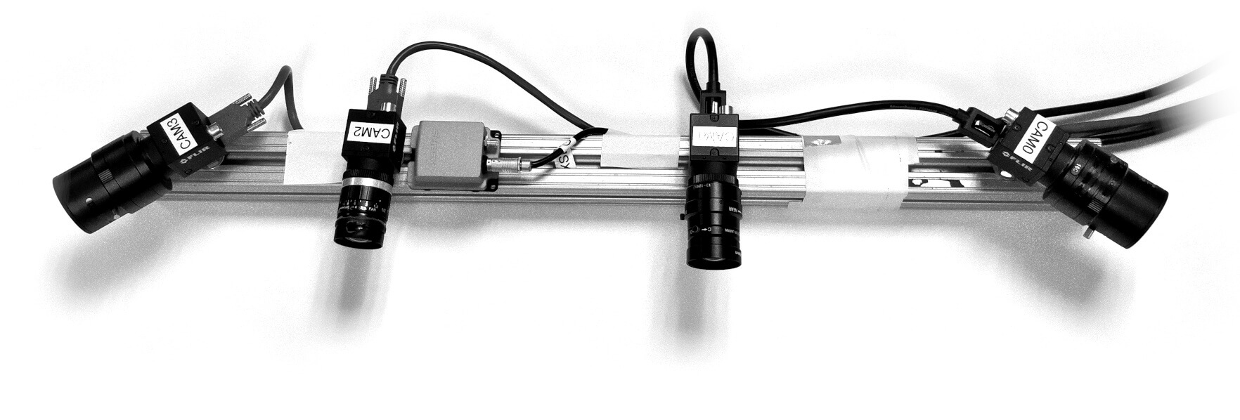
Visual-Inertial Sensors
One may ask why use a visual-inertial sensor? The main reason is because of the complimentary nature of the two different sensing modalities. The camera provides high density external measurements of the environment, while the IMU measures internal ego-motion of the sensor platform. The IMU is crucial in providing robustness to the estimator while also providing system scale in the case of a monocular camera.
However, there are some challenges when leveraging the IMU in estimation. An IMU requires estimating of additional bias terms and requires highly accurate calibration between the camera and IMU. Additionally small errors in the relative timestamps between the sensors can also degrade performance very quickly in dynamic trajectories. Within this OpenVINS project we address these by advocating the online estimation of these extrinsic and time offset parameters between the cameras and IMU.
Video Walkthrough Guide to Calibration
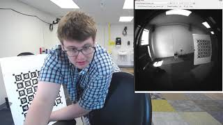
This first video walks through the process of performing visual-inertial sensor calibration and is a complete overview of the below text. The video was recorded in a single session from start to finish, so please use the chapters to skip to the sections which are of interest. The sensor used is the Intel Realsense D455 color camera and internal IMU. The key software used is Kalibr and allan_
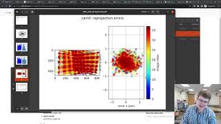
In this video takes from having a sensor, to collecting data, performing calibration, and finally processing that data live with OpenVINS to recover a 6dof pose estimate. The later part is similar to the Simple Tutorial but is for a live sensor. First we create a launch file for the Intel Realsense T265 sensor, after which we perform calibration. Finally we use the calibration to process data with OpenVINS and demo the recovered trajectory.
Camera Intrinsic Calibration (Offline)
The first task is to calibrate the camera intrinsic values such as the focal length, camera center, and distortion coefficients. Our group often uses the Kalibr [15] calibration toolbox to perform both intrinsic and extrinsic offline calibrations, by proceeding the following steps:
- Clone and build the Kalibr toolbox
- Print out a calibration board to use (we normally use the Aprilgrid 6x6 0.8x0.8 m (A0 page) pdf yaml)
- Ensure that your sensor driver is publishing onto ROS with correct timestamps.
- Sensor preparations
- Limit motion blur by decreasing exposure time (can be achieved through high framerate)
- Ensure that your calibration board can be viewed in all areas of the image
- Ensure that your sensor is in focus (can use their
kalibr_camera_focusor just manually)
- Record a ROS bag and ensure that the calibration board can be seen from different orientations, distances, and in each part of the image plane. You can either move the calibration board and keep the camera still or move the camera and keep the calibration board stationary.
- Finally run the calibration
- Use the
kalibr_calibrate_cameraswith your specified topic - We recommend filtering the bag with their
--bag-freq 10.0to reduce the processing time - Depending on amount of distortion, use the pinhole-equi for fisheye, or if a low distortion then use the pinhole-radtan
- Depending on how many frames are in your dataset this can take on the upwards of a few hours.
- Use the
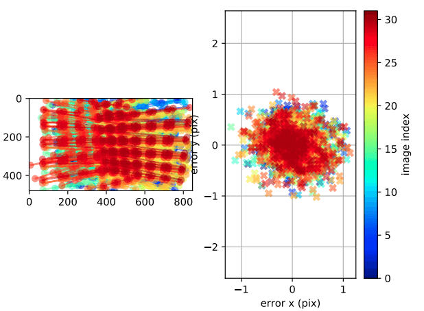
- Inspect the final result, pay close attention to the final reprojection error graphs, with a good calibration having less than < 0.2-0.5 pixel reprojection errors. If you are planning on performing online calibration of the camera, then larger values might be acceptable (e.g. 1 pixel), but a more accurate offline calibration is always preferred.
An example script calibrate_
IMU Noise Calibration (Offline)
The other important intrinsic calibration is to compute the inertial sensor intrinsic noise characteristics, which are needed for the batch optimization to calibrate the camera to IMU transform and in any VINS estimator so that we can properly probabilistically fuse the images and inertial readings. Specifically we are estimating the following noise parameters:
| Parameter | YAML element | Symbol | Units |
|---|---|---|---|
| Gyroscope "white noise" | gyroscope_noise_density | ||
| Accelerometer "white noise" | accelerometer_noise_density | ||
| Gyroscope "random walk" | gyroscope_random_walk | ||
| Accelerometer "random walk" | accelerometer_random_walk |
The standard way as explained in [IEEE Standard Specification Format Guide and Test Procedure for Single-Axis Interferometric Fiber Optic Gyros (page 71, section C)] is that we can compute an Allan variance plot of the sensor readings over different observation times (see below).
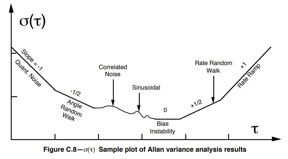
As shown in the above figure, if we compute the Allan variance we we can look at the value of a line at with a -1/2 slope fitted to the left side of the plot to get the white noise of the sensor. Similarly, a line with 1/2 fitted to the right side can be evaluated at to get the random walk noise.
We recommend using the allan_
- Clone and build allan_
variance_ ros - Ensure that your sensor driver is publishing onto ROS with correct timestamps.
- Collect a stationary dataset on the upwards of 20 hours
- Finally run the calibration
- Construct a config file with the IMU topic, sensor rate, and datset time
- Generate the allan variance data files with teh
allan_variancecommand - Finally process the command via their
analysis.pyscript
- Typically these noise values should be inflated by maybe 10-20x their values to take into account unmodelled errors (one can test to see how different inflations perform)
An example script calibrate_
Dynamic IMU-Camera Calibration (Offline)
After obtaining the intrinsic calibration of both the camera and IMU, we can now perform dynamic calibration of the transform between the two sensors. For this we again leverage the [Kalibr calibration toolbox]. For these collected datasets, it is important to minimize the motion blur in the camera while also ensuring that you excite all axes of the IMU. One needs to have at least one translational motion along with two degrees of orientation change for these calibration parameters to be observable (please see our recent paper on why: [Degenerate Motion Analysis for Aided INS With Online Spatial and Temporal Sensor Calibration]). We recommend having as much change in orientation as possible in order to ensure convergence.
- Clone and build the Kalibr toolbox
- Print out a calibration board to use (we normally use the Aprilgrid 6x6 0.8x0.8 m (A0 page) pdf yaml)
- Ensure that your sensor driver is publishing onto ROS with correct timestamps (inspect the IMU time dt plot carefully in the PDF report!)
- Sensor preparations
- Limit motion blur by decreasing exposure time
- Publish at high-ish framerate (20-30hz)
- Publish your inertial reading at a reasonable rate (200-500hz)
- Record a ROS bag and ensure that the calibration board can be seen from different orientations, distances, and mostly in the center of the image. You should move in smooth non-jerky motions with a trajectory that excites as many orientation and translational directions as possible at the same time. A 30-60 second dataset is normally enough to allow for calibration.
- Finally run the calibration
- Use the
kalibr_calibrate_imu_camera - Input your static calibration file which will have the camera topics in it
- You will need to make an imu.yaml file with your noise parameters.
- Depending on how many frames are in your dataset this can take on the upwards of half a day.
- Use the
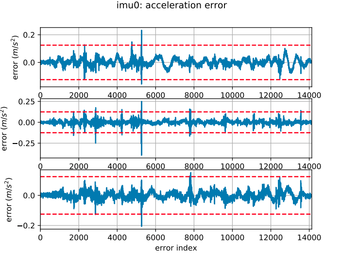
- Inspect the final result. You will want to make sure that the spline fitted to the inertial reading was properly fitted. Your accelerometer and gyroscope errors are within their 3-sigma bounds (if not then your IMU noise or the dataset are incorrect). Ensure that your estimated biases do not leave your 3-sigma bounds. If they do leave then your trajectory was too dynamic, or your noise values are not good. Sanity check your final rotation and translation with hand-measured values.
An example script calibrate_